Formula Racing at UC Davis (FSAE Electric)
What is Formula Racing SAE Electric?
Formula SAE Electric is a design and engineering challenge for university students designed and run by the Society of Automotive Engineers. The goal of the competition is to design and build an open-wheel, single-seat, electric racecar conforming to a stringent set of rules, which emphasize drivetrain innovation, safety, and energy efficiency in a high-performance application. Our team’s cost, design, and strategic positioning decisions are made to take into account the interests and requirements of a weekend autocross racer. These decisions are then presented to a panel of industry professionals in the business presentation.
Below you can find my projects for the Formula Racing at UC Davis club. I invite you to dive deeper into my work and gain insight into my skills and aspirations as an engineer.
Role:
As the lead drivetrain engineer, my responsibility was to design, manufacture and integrate a new high-voltage drivetrain architecture that maximizes powertrain efficiency and performance. Drivetrain consists of packaging the motor, motor controller, and differential. I constantly apply concepts from my previous courses like statics, mechanics of materials, properties of materials, and manufacturing processes.
Role:
As a powertrain engineer, my responsibility was to aid in the design, manufacture and integration of a high-voltage powertrain. The powertrain team consisted of the drivetrain, battery pack, and water cooling system. I would help work on projects from each of these subteams depending on the team's needs.
Lead Drivetrain Engineer (2022-2024)


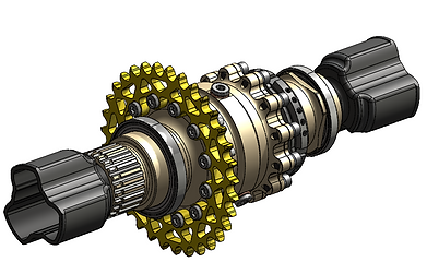
Below is the drivetrain that was manufactured during the 2022-2023 season!
The 2022-2023 season marks the first season our team has incorporated a new drivetrain architecture. This year we are using the EMRAX 228 HV LC motor and CM200DZ Inverter, which produce 40% more torque and power over the previous architecture. Our differential is the Drexler adjustable limited slip differential which allows for our torque to be split and allocated to the wheel with highest traction.
Gearing:
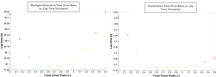
Having selected the components that power the drivetrain, the first step was to determine the Final Drive Ratio (FDR) of the vehicle. This is the ratio between the driving sprocket and driven sprocket. We use a roller chain drive design for our vehicle due to it's simplicity, high efficiency and reliability. When selecting a Final Drive Ratio there are many factors to consider. The first thing to consider is the type of track upon which you will be racing. FSAE tracks are shorter in length with multiple tight turns, which means your vehicle will not have the ability to reach high speeds. In this case, a higher torque is preferable to more effectively go out of tight corners. It's important to then take into account the tractive limits of your car. There is only so much torque that

your vehicle can put down on the ground efficiently before your tire loses grip and slips. You want determine a FDR that will push the tractive force to the tractive limit and even slightly above to give your driver the ability to use all the torque possible without slippage. Another thing to consider is the efficiency of the motor which changes depending on the RPM your motor is running at. FSAE gives points for vehicles with the highest efficiency, so it's important to select a FDR that will place your motor in a high efficiency range when racing. Taking these consideration into account, I determined the FDR ratio to be 2.75 using OptimumLap track simulation. The software takes into account vehicle parameters, ranging tire data to motor curve data and identifies the optimal FDR based on which completes the race in a faster time. Below I have provided a couple lap time simulation I ran to determine the FDR.
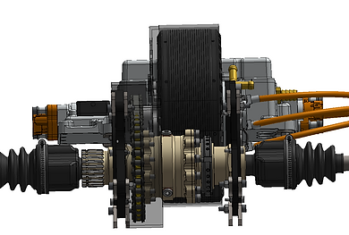
Packaging Solution:
My next step is to determine a packaging solution for the motor and differential. There are two different approaches: package each component separately or package both components together. In our case, we determined that having a separate mounting solution did not produce the required stiffness causing large displacement in the system. With the help of Finite Element Analysis at an assembly level, a single mounting solution between the motor and differential was made.


Differential Sprocket:
Unlike previous years, the differential sprocket was mounted directly onto the Drexler differential and is therefore on the inside of the planes of the support brackets The differential sprocket is held by 12 low profile M6 SHCS at a calculated torque of 10Nm per fastener. This simplified the manufacturing & packaging process, alongside reducing weight by removing the extra adapter used to mount the sprocket to the differential.
Motor Shaft:
The EMRAX 228 provides a motor shaft that is not ideal for our loading application. A custom motor shaft had to be designed for our loading application. Before I could get to the final design of a motor shaft, I had to
understand the type of motor in hand and loading the motor would undergo. The EMRAX 228 is
an axial flux motor in which the entire casing of the motor rotates around the stator. The motor
will power our wheels through a chain drive system which will put a shear load on the shaft. I
calculated the load applied by the chain drive system using a MATLAB script. With an
understanding of the loading and setup, I began the design of the motor shaft. The challenge
was to incorporate a sprocket and extra bearing on the shaft for support. The shaft was created
using a key that would allow a sprocket with a key slot to attach to the shaft. The advantage of
using a key and key slot compared to splines or an incorporated sprocket is the complexity level
of manufacturing being lower. A machined sprocket can be purchased heat treated at a very
low cost while the production of splines is more complex and high in price. The motor is not
designed for the type of loading seen on a chain drive system. I ran multiple assembly level
static FEA simulations which confirmed the need for extra support due to the high displacement
in the system. How could this be limited, well I decided to add a bearing at the end of the shaft
to attach a support bracket. To reduce the displacement in the system more, I reduced the
length of the shaft which will reduce the moment being created. As a result, the final motor shaft
consists of a design that incorporates a method to transfer torque in the system through the
sprocket and has the appropriate support needed to prevent failure in the part.

Drivetrain Engineer (2020-2022)
Below are the projects I worked on as a powertrain engineer on the team.
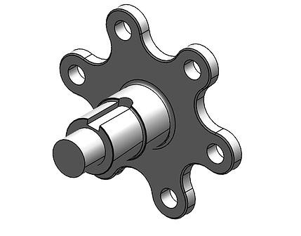
Tripod Housing:
The last step to transfer torque to the wheels is the tripod housing on the wheel. For this project, the goal was to redefine the contact area between the roller on the tripod joint and the surface of the tripod housing. The team had been running a rectangular contact area between two spheres leading to inaccurate results in our simulations. Having found the new contact area, I then designed and manufactured the the tripod housing that connects to the wheel hub.
Project Goal:
Contact Area:
The contact between the roller on the tripod joint and the tripod housing is that of a sphere with a concave sphere. The contact between these two surfaces will create a circular contact area of a diameter equal to 2a. The stress will be highest at the center point where contact is made and will have a semi-elliptical pressure distribution. The first step to finding the Hertzian contact stress, is to identify the diameter of the contact area. The radius a can be determined using equation 1 below. To do so, we must know the Force being applied, Poisson's Ratio, Elastic Modulus and the diameters for the tripod housing and the roller of the tripod joint. Having these values, I was then able to calculate the contact radius, are and maximum contact pressure using the following MATLAB script.
Contact Area Equation:


Contact Area MATLAB Script:
Tripod Housing Design and Rear Wheel Package Assembly:
Tripod Housing Design: Rear Corner Assembly with Outboard Tripod Housing:


Features:
-
7075-T6 Aluminum Body
-
Six, 1144 Carbon Steel sheer pins
-
O-Ring Grease Seal
Tripod Housing FEA:

GD&T:
